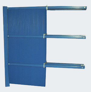
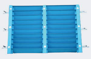
We provide a packing list of the components supplied along with distances at which horizontal stiffeners are to be fixed to side walls.
-
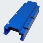
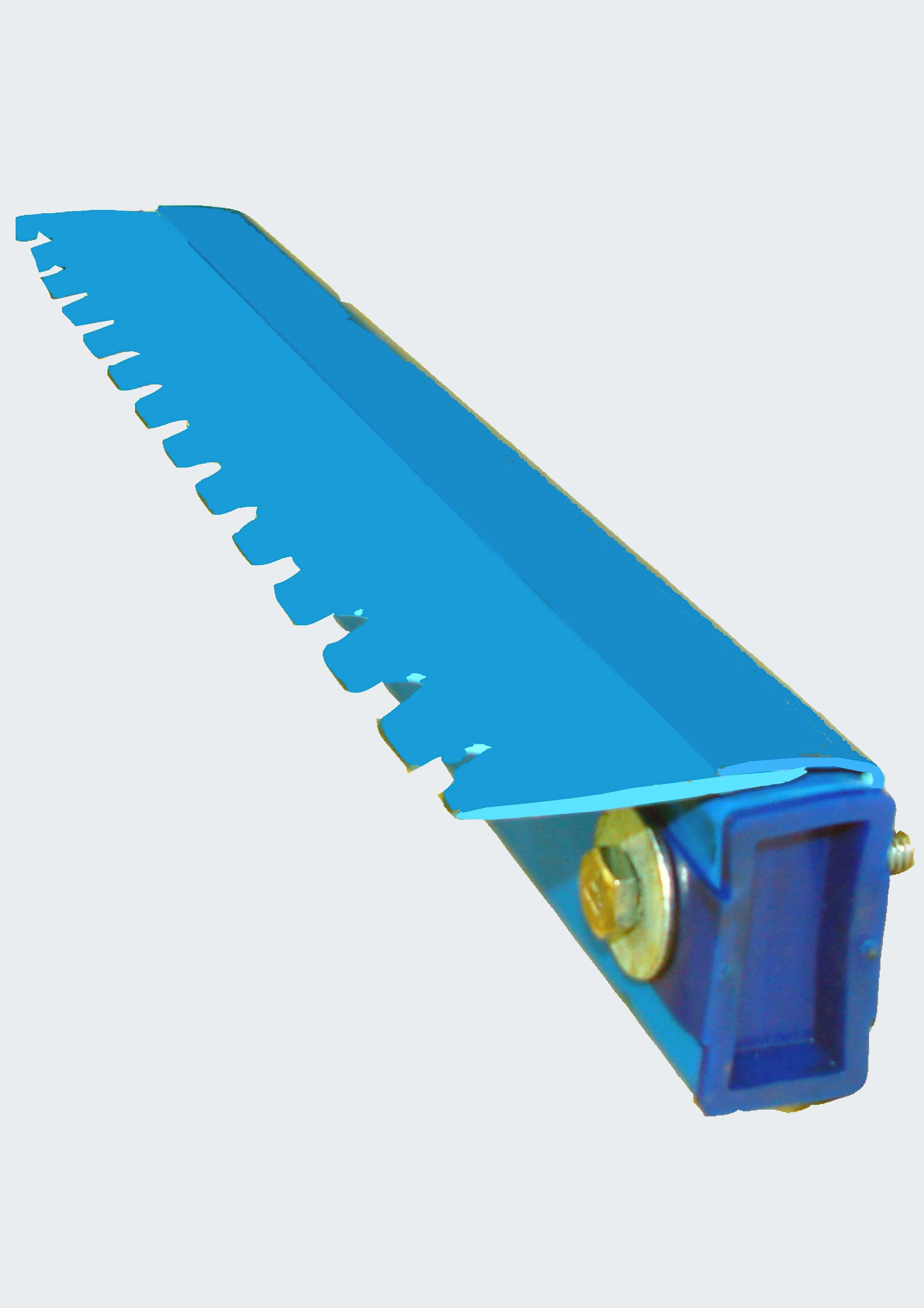
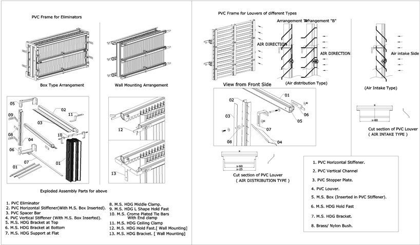
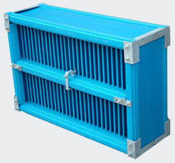
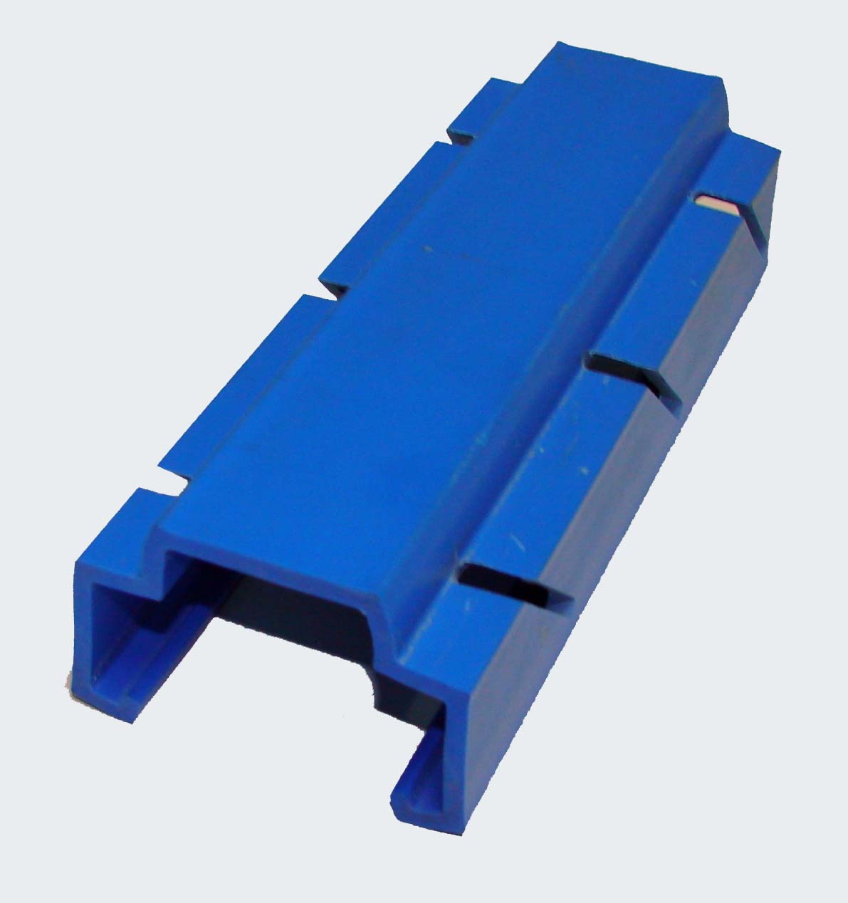
- G-Channel – To fix up Louvers Slotting at 60mm / 75mm Pitch of Louver can be attached as per requirements.
-
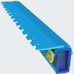
- Stiffener – With M.S. inserted and sealed at both end Spacer bar with suitable notching as per Eliminator profile.